Alien 5Ӧ
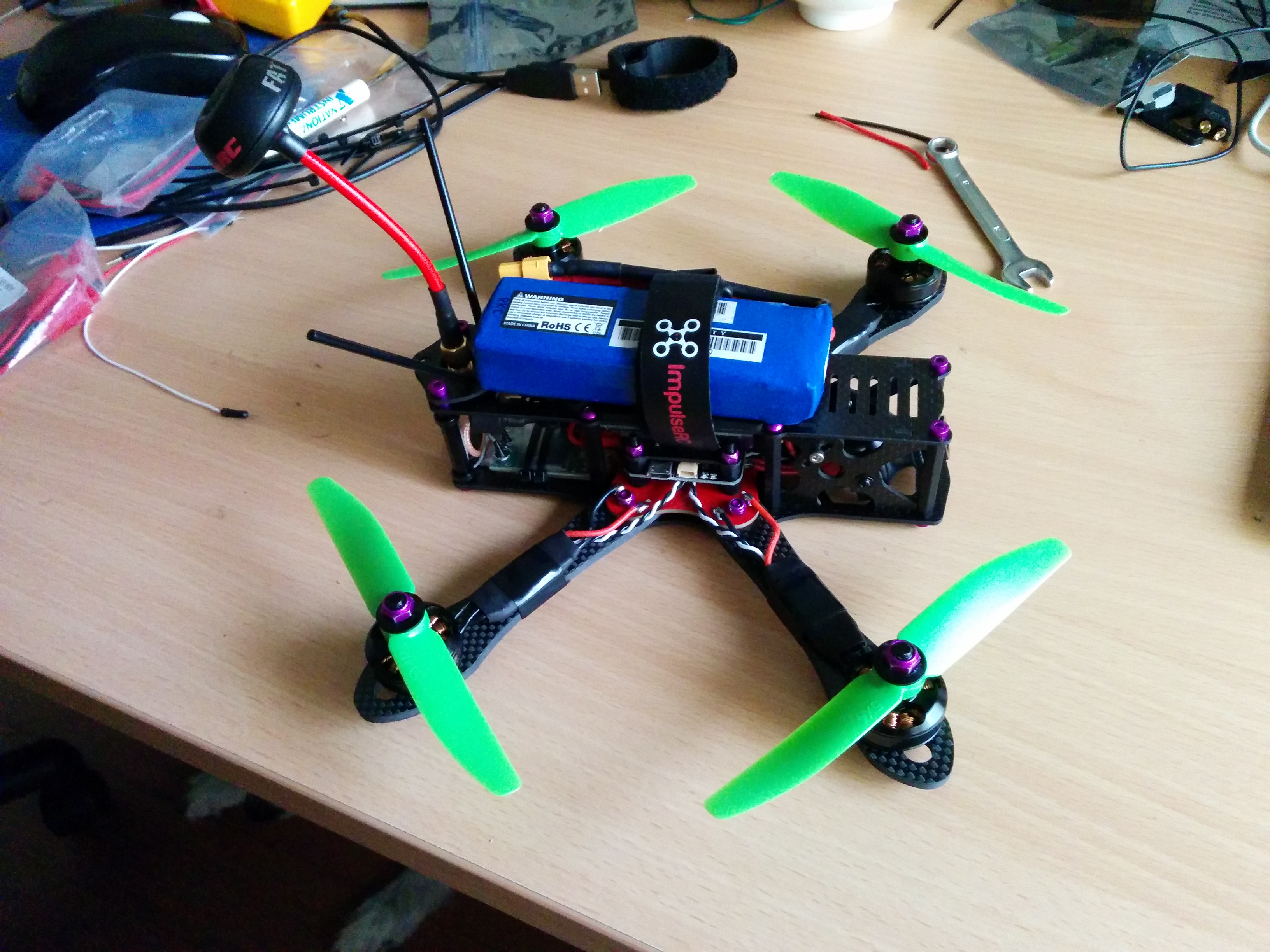
The Alien is produced by ImpulseRC. From my perspective this is a high quality product. The engineering is really good, lots of thought has gone into this product from the designers.
Parts
| Part | Description |
|---|---|
| Frame | Alien 5” (225mm) |
| FC | Motolab Tornado STM32F3 (Betaflight 2.4.0) |
| ESC | FVT LittleBee 20A (BLHeli) |
| Motors | Cobra 2204 2300kv |
| Propellors | 5040 HQProp |
| Receiver | Storm S603 (Spectrum Compatible) |
| Flight Camera | Surveilzone HS1177 Sony Super HAD II 600TVL |
| Video Transmitter | ImmersionRC 5.8GHz 200mW Video Transmitter |
| VTX Antenna | FatShark 5.8 GHz SpiroNET RHCP |
| On-Screen Display | |
| Batteries | Zippy 1800mAh 3s 40C |
| Voltage Regulators | 5V Polulu D24V5F5 (powering FC) 12 BEC (powering camera) |
| Goggles | FatShark Attitude V3 FPV Goggles |
| VRX Antenna | FatShark 5.8 GHz SpiroNET RHCP |
| Transmitter | Spektrum DX6i |
As I don’t have an OSD yet I have added a buzzer to provide a low battery warning. I have to fly it near me occasionally to hear it. It is surpisingly loud. I got a 9V - 14V buzzer and connected to the Lipo and buzzer signal pins on the FC.
Flight Controller
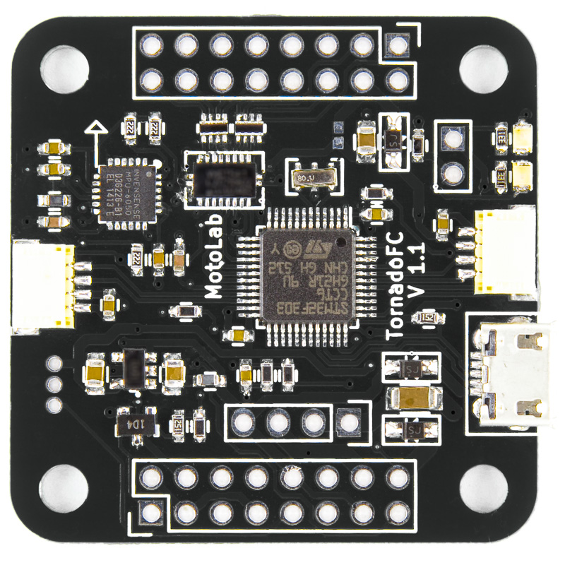
I am using the MotoLab Tornado F3 Flight Controller from ImpulseRC.
There are three separate power rails on the board.
Lipo voltage - Connected to a resistor network for VBAT monitoring and to the pads for an external switching regulator. 5V - Connected to the external regulator output, internal 3.3V regulator input, 5V PWM buffer, and external device interfaces including the SBUS and PPM receivers, 5V buzzer, serial LED and RSSI. 3.3V - Powers the CPU and gyro chip as well as the external DSM2/DSMX receiver on the SAT connector.
The Tornado does not have an on-board 5V regulator. 5V power may be sourced from an ESC BEC or from an external switching regulator. The board’s 5V rail is expected to be provided by an external 5V regulator. ImpulseRC sell a 5V Polulu regulator to fulfill this need that perfectly fits the dedicated through-hole connectors provided for a 5V regulator.
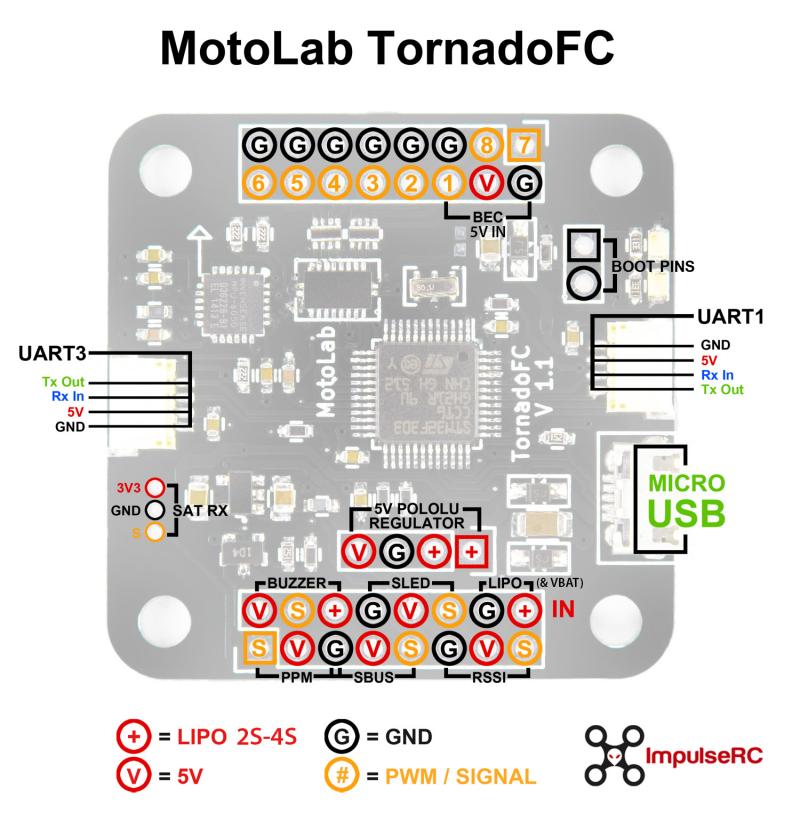
Pinout Notes
- Pins marked “+” are LIPO voltage. LIPO input voltage is limited to 6S, depending on the regulator used. Pololu recommends an external 33uF 50V capacitor for over 20V inputs.
- The LIPO IN pins are connected internally to the VBAT monitor.
- Pins marked “V” are +5V ONLY. Do not connect anything over 5V to these pins.
- All of the numbered pins are PWM outputs.
- The LIPO “+” and BEC “V” pins have reverse-current blocking diodes to prevent powering ESCs from USB power.
- To bypass the BEC “V” input diode and output 5V on this pin, short the two-pad jumper below the PWM 1 input.
- The Pololu switching regulator may be mounted on top or bottom of the board. Observe the orientation.
- If using an external 5V BEC of any kind (including a Pololu not mounted on the board), connect it to the pins labelled “BEC 5V IN”.
- SAT RX and SBUS use UART 2.
- The “S” pin on the buzzer connection is the switched ground. Connect the + pin of the buzzer to either the lipo “+” or 5V “V” pin, and the - pin to “S”.
SmartPort Telemetry
Cleanflight and Betaflight can send Smartport telemetry to the FrSky X-series receivers over a single wire. Connect TXOUT from either serial port to the S.PORT pin on the receiver. It only takes one wire because the ground connection is already made with the SBUS cable. The voltage divider for lipo monitoring is built into the Tornado.
To enable lipo monitoring over Smartport:
Enable VBAT and Telemetry on the Config tab Select Telemetry -> SmartPort and AUTO on the ports tab Set telemetry_inversion=on in CLI (This is the default in later firmware)
The lipo voltage shows up in OpenTX as VFAS. The most useful telemetry parameters seem to be VFAS, RSSI, and RxBt (receiver input voltage).
Firmware
The Motolab Tornado F3 comes with a version of Betaflight already installed. This is fine to use but it is recommended to run the most recent version. This will have fixes as well as new features.
The Motolab Tornado presents itself as a USB device that supports DFU programming. DFU allows devices to have their firmware downloaded and uploaded over a USB transport. To put the Motolab Tornado F3 into bootloader mode, bridge the boot pins and connect the board to the USB. The bridge only needs to be made as the USB connection is made and can be removed after.
Once I enabled AIR_MODE I noticed that the quad would bob and bounce when I tried to land. These issues seems to have been encountered by many others. Until I find a good solution I bring the quad in close to the ground and then quickly disarm it as I land.
A good example was captured in this YouTube video:
Instructions
- Go to the betaflight releases page.
- Download the betaflight_MOTOLAB.hex file.
- Open CleanFlight Configurator.
- Bridge the boot pins and connect the Tornado F3 to the USB.
- The ‘device’ pull-down on Cleanflight Configurator should change to DFU.
- Select the Firmware-Flasher tab.
- Click the Load Firmware [Local] button and choose the betaflight_MOTOLAB.hex file just downloaded.
- Click the Flash Firmware button and observe the progress bar and status.
Your FC should now be flashed with the latest betaflight firmware.
Configuration
Modes: AIR_MODE, ACRO_PLUS
Electronic Speed Controller (ESC)
I am currently using the FVT LittleBee 20A ESC.
Batteries
As I have 20A ESC’s I need to be looking for a battery capable of discharging at least 80A. So, I should be looking for a minimum of something along the lines of:
- 1300mAh 65C
- 1800mAh 45C
From my previous ZMR250 I have 3 Zippy 1800mAh 3S 40C batteries. The batteries that I’m using on my ZMR250, Zippy 40C (50C burst) 1800mAh should be OK as a stop-gap until I get more suitable batteries for this quad setup.
I recently got 3 Turnigy A-Spec 4S 1300 mAh 60C to use with this Alien build. I notice some power improvement. I also notice that there is terrible noise on my FPV video when running these batteries. I have a cheap 12V BEC that supplies the camera power which I am suspecting is the culprit of the noisy signal that is causing the video problems.
More recently I purchased 6 Dinogy 4S batteries. 3 1300 mAh and 3 18mAh.
Receiver
I am using a S603 Receiver
Video Transmitter
I am using the ImmersionRC 5.8GHz 200mW Video Transmitter.
FPV Goggles
I am using the FatShark Attitude V3 FPV Goggles.
Transmitter Configuration
I am using a Spektrum DX6i transmitter. The transmitter requires some adjustment so as to configure the mid-points of the channels around the 1500 value and to configure the channel span to support approximately 1000 - 2000 as expected by Cleanflight.
The Motolab Tornado F3 can drive the receiver when powered by USB which is convenient, meaning I don’t need to plug in the battery to configure the flight controller.
So, I connect the quad to Cleanflight Configurator, turn on the transmitter then go to the receiver tab. In here I can see if the channels are configured correctly.
When its all configured correctly I’m expecting to see the values move right when I move the pitch up, the roll right and the yaw right. Initally the values were not spanning the ranges expected by Cleanflight and some of the channels moved the wrong way.
Reverse Channels
Reverse Aileron and Rudder in Transmitter so that moving stick right on transmitter moves the channel slider right in Cleanflight.
Travel Adjust
Adjust throttle travel to span approximately 1000 - 2000 in Cleanflight. To achieve this I adjusted the travel as well as modify the sub-trim.
- Throttle: +109%
Sub-Trim
Adjust sub-trim in Transmitter so that Roll, Pitch and Yaw have a minimum around 1020 and are centered around 1500.
- Throttle: down 27
- Aileron: left 29
- Elevator: down 28
- Rudder: left 54
Once these settings are made I noted the minimum and maximum throttle values and then went back into the Configuration tab to update the min and max throttle values.
When this was all done I could successfully arm and disarm the motors by using the standard approach:
- Arm: min throttle and yaw right.
- Disarm: min throttle and yaw left.
Mix three switches on the transmitter into the Flaps channel to output onto channel 6 (e.g Aux2) channel. Using this configuration we can get four positions (0%, 25%, 75%, 100%). The Flap switch overrides the mix switches.
Enter the ADJUST LIST menu by clicking the scroll button.
Enter the FLAPS option and configure it as follows:
FLAPS

     FLAP  ELEV
NORM ^100     0
LAND v100     0
Exit the FLAPS menu.
Enter the MIX1 menu. The goal here is to alter the settings such that when the MIX switch is off the GEAR switch moves between GPS and Manual and when the MIX switch is on the GEAR switch moves between GPS and Attitude modes. Flip the MIX and GEAR switch on and modify the settings until the Attitude mode is selected.
     MIX1

FLAP>   FLAP ACT
Rate D    0% U - 90%
SW ELEV D/R  TRIM ACT
Exit the MIX1 menu.
Enter the MIX2 menu. The goal here is to configure the settings such that the Failsafe mode is selected irrespective of whether the Control Mode was GPS, Attitude or Manual.
     MIX2

FLAP>   FLAP ACT
Rate D    0% U - 55%
SW AIL  D/R  TRIM ACT
Exit the MIX2 menu.
The resulting setup operates as follows:
| Switch | Value |
|---|---|
| None | 0 % |
| AIL D/R | 25 % |
| ELEV D/R | 50 % |
| AIL D/R + ELEV D/R | 75 % |
| Flaps | 100 % |
I use the Gear switch to switch between Angle mode and Acro mode. This is mostly just in case I get into trouble I can quickly switch into a self levelling mode.
I use the Flap switch to enable Air Mode and Acro Plus mode.
I use the AIL switch to enable the beeper mode. I still use the sticks to arm and disarm and I have found that by simply holding the stick in the disarm position will trigger the beeper to go off. This is just as good as the beeper mode.
FPV Camera
With this quad setup I am using the Surveilzone HS1177 Sony Super HAD II 600TVL. However, this unit is a custom unit from ImpulseRC. I think the only difference from the standard HS1177 is that the ImpulseRC version has the cable connector at the top left of the back instead of at the bottom.
The build instructions produced by ImpulseRC on their Youtube channel show the camera being powered by the 5V regulated power output from a ImmersionRC Video Transmitter. I am using the same video transmitter.
However, I found my camera just didn’t produce a video signal when using this configuration. I would just see a black screen in my goggles. This was a real annoyance.
Removing all variables, I supplied the camera with 5V from a wall power pack and connected it to my TV. The video signal would briefly show a picture before blanking out then it would repeat this sequence forever. If I increased the power to 9V then the video signal was steady and reliable.
I had a ZMR250 PDB laying around so I removed the small 12V regulator BEC from that, packaged it up nicely so it could sit in-line between the battery and the camera. Physically it connects to the Alien PDB via JST connectors and sits between the camera and the flight controller stack.
I guess one good thing about this is that I should be able to run 3S and 4S batteries without damaging the Camera. Apparently the camera has a known issue running above 16V even though it states that it supports up to 22V.
When I use 4S batteries on with this 12V regulator I noticed that there is extra artefacts on my FPV video. The video image is still clear enough to fly with but there are undesirable horizontal lines across the screen of light and dark zones that progressively scan down. I am suspecting is the culprit of the noisy signal is the 12V regulator.
Settings
Controller: Luxfloat Looptime: ?
| PID | P | I | D |
|---|---|---|---|
| Roll | 1.5 | 0.04 | 20 |
| Pitch | 1.5 | 0.04 | 20 |
| Yaw | 4.0 | 0.04 | 10 |
Betaflight 2.6.0 Update
Controller: Luxfloat
| PID | P | I | D |
|---|---|---|---|
| Roll | 4.5 | 0.03 | 18 |
| Pitch | 4.5 | 0.03 | 18 |
| Yaw | 4.0 | 0.03 | 0 |
Rates
| Rates | Value |
|---|---|
| Roll Rate | 0.70 |
| Pitch Rate | 0.70 |
| Yaw Rate | 0.50 |
| TPA | 0 |
| TPA Breakpoint | 1500 |
LED Ring
The Alien supports an optional LED ring that is placed at the rear of the quad.
I came across a flitetest forum post that covered the LED ring in ome detail.
From there I came across a good youtube video showing it off.
Properllors
So far I have used the following propellors on this build.
One motor would keep spinning after stopping. Backed off screws a little and all good.